Ниже представлена схема датчика движения с использованием Arduino. В качестве датчика, мы будем использовать PIR-сенсор (Passive Infrared sensor), т.е. пассивный ИК датчик. PIR-сенсоры основаны на методике измерения инфракрасного излучения от обьектов.
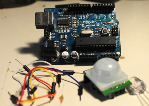
Итак, для создания ИК датчика движения нам понадобятся следующие компоненты:
контроллер Arduino
макетная плата
1 светодиод
PIR сенсор фирмы Parallax
провода
Схема подключения датчика движения (PIR) к контроллеру Arduino простейшая:
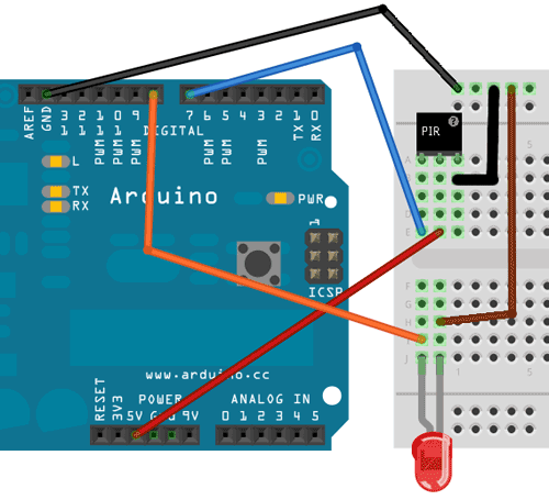
PIR-сенсор имеет 3 вывода: плюс, минус и выход. К 7-му выводу Arduino подключаем выход PIR-сенсора. Также, присоединим светодиод к выводу 8 Arduino и GND.
Исходный код программы взят с официального сайта arduino.cc:
/* * ////////////////////////////////////////////////// * //making sense of the Parallax PIR sensor's output * ////////////////////////////////////////////////// * * Switches a LED according to the state of the sensors output pin. * Determines the beginning and end of continuous motion sequences. * * @author: Kristian Gohlke / krigoo (_) gmail (_) com / http://krx.at * @date: 3. September 2006 * * kr1 (cleft) 2006 * released under a creative commons "Attribution-NonCommercial-ShareAlike 2.0" license * http://creativecommons.org/licenses/by-nc-sa/2.0/de/ * * * The Parallax PIR Sensor is an easy to use digital infrared motion sensor module. * (http://www.parallax.com/detail.asp?product_id=555-28027) * * The sensor's output pin goes to HIGH if motion is present. * However, even if motion is present it goes to LOW from time to time, * which might give the impression no motion is present. * This program deals with this issue by ignoring LOW-phases shorter than a given time, * assuming continuous motion is present during these phases. * */ ///////////////////////////// //VARS //Время калибровки датчика (10-60 сек. по даташиту) int calibrationTime = 30; //the time when the sensor outputs a low impulse long unsigned int lowIn; //the amount of milliseconds the sensor has to be low //before we assume all motion has stopped long unsigned int pause = 5000; boolean lockLow = true; boolean takeLowTime; int pirPin = 7; //вывод подключения PIR сенсора int ledPin = 8; ///////////////////////////// //SETUP void setup(){ Serial.begin(9600); pinMode(pirPin, INPUT); pinMode(ledPin, OUTPUT); digitalWrite(pirPin, LOW); //дадим датчику время на калибровку Serial.print("calibrating sensor "); for(int i = 0; i < calibrationTime; i++){ Serial.print("."); delay(1000); } Serial.println(" done"); Serial.println("SENSOR ACTIVE"); delay(50); } //////////////////////////// //LOOP void loop(){ if(digitalRead(pirPin) == HIGH){ digitalWrite(ledPin, HIGH); //the led visualizes the sensors output pin state if(lockLow){ //makes sure we wait for a transition to LOW before any further output is made: lockLow = false; Serial.println("---"); Serial.print("motion detected at "); Serial.print(millis()/1000); Serial.println(" sec"); delay(50); } takeLowTime = true; } if(digitalRead(pirPin) == LOW){ digitalWrite(ledPin, LOW); //the led visualizes the sensors output pin state if(takeLowTime){ lowIn = millis(); //save the time of the transition from high to LOW takeLowTime = false; //make sure this is only done at the start of a LOW phase } //if the sensor is low for more than the given pause, //we assume that no more motion is going to happen if(!lockLow && millis() - lowIn > pause){ //makes sure this block of code is only executed again after //a new motion sequence has been detected lockLow = true; Serial.print("motion ended at "); //output Serial.print((millis() - pause)/1000); Serial.println(" sec"); delay(50); } } }
В скетче Arduino видно, что датчик проводит самодиагностику, а затем переходит в режим отслеживания движений. Когда движение обнаружено, то загорается светодиод. По Serial Monitor вы можете отслеживать сколько по времени длилось движение.
Данный проект можно использовать как основу для обнаружения движения в охранных сигнализациях, для включения освещения, в робототехнике и т.п.
Оригинал статьи на английском языке (перевод Колтыков А.В. для сайта cxem.net)